Installation tips

PolTherma CS – PU panel installation

TECHNICAL INFORMATION ON THE METHOD OF APPLICATION OF SEALING FOAM AT THE PANEL JOINT PolTherma CS
Version for panels with Standard CS (unfilled) joint
In the case of PolTherma CS series refrigeration panels to be installed vertically, special preparation of the panel joint for sealing foam application is recommended.

To prepare the joint surface, you will need:

  • sponge;
  • water;
  • water sprayer – pressure sprayer;
  • Low-pressure, closed-cell polyurethane foam, preferably recommended by Europanels;
  • foam gun (for better control of the application, hose foams are not recommended).

Before installation, make sure that the cylinders of foam to be applied are at the right temperature (not less than room temperature). Do not apply the foam frozen!

1.
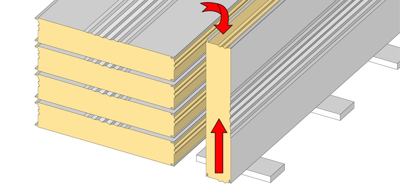
Take the plate from the package, place the longer side on a surface protected with polystyrene spacers. The panel tongue (steel locking element) are to face upward.

2.
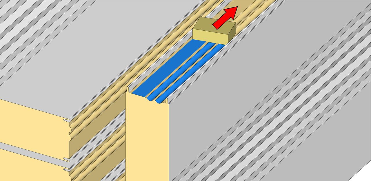
Lightly moisten the foam surface at the joint with a damp sponge (along the entire length of the board) to improve the adhesion of the applied foam. Do not allow water streaks to remain on the joint surface – the joint is to be moist, not flooded with water.

3.
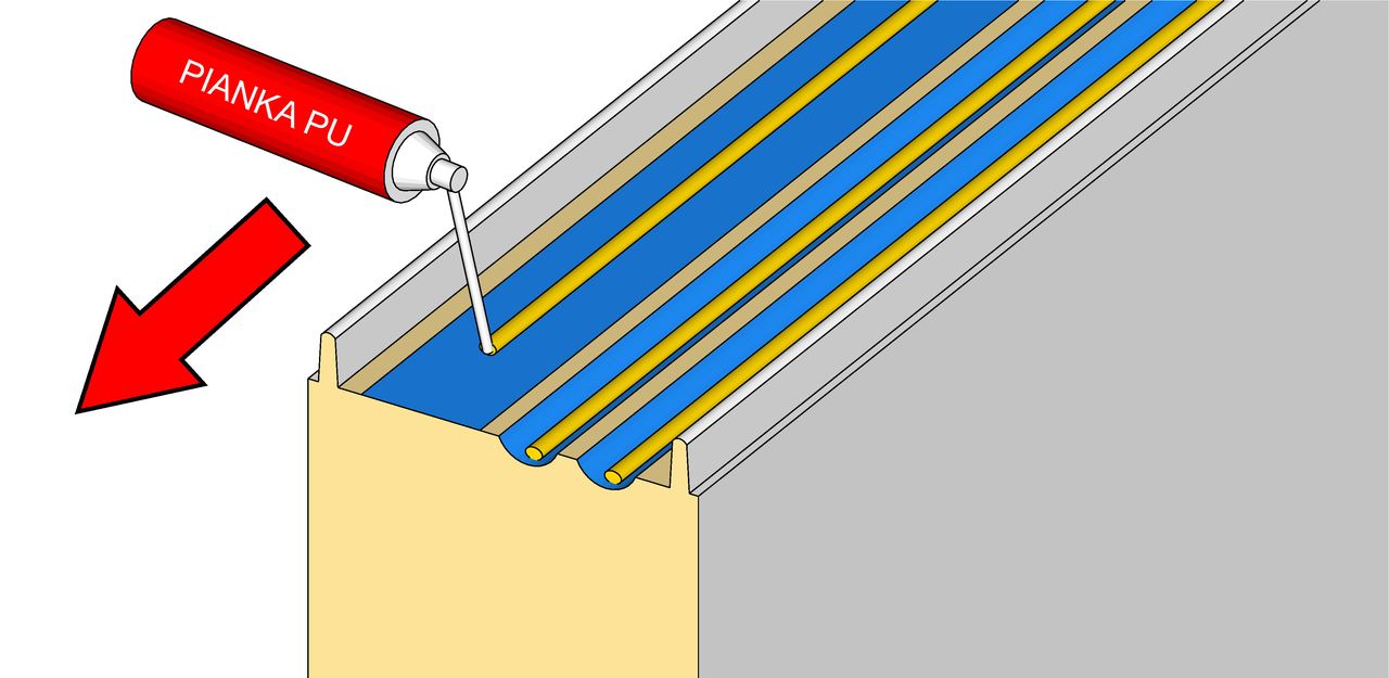
Apply 3-4 braids of foam with a small diameter (max 10mm each): one each in the contact recesses and one or two (CS200) on the flat part. Do not apply too much foam!

4.
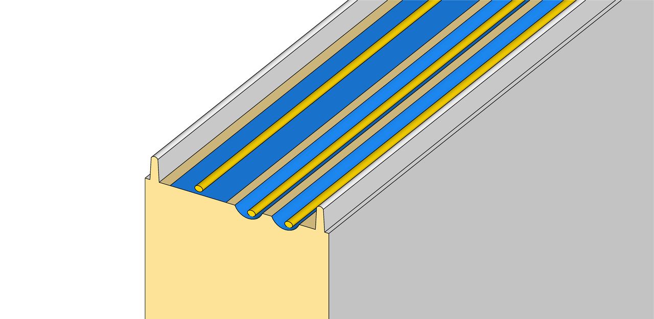
Using a sprayer, lightly moisten the surface of the applied foam with water and wait until its surface hardens, i.e. until the formation of the so-called crust, which does not adhere on contact.

5.
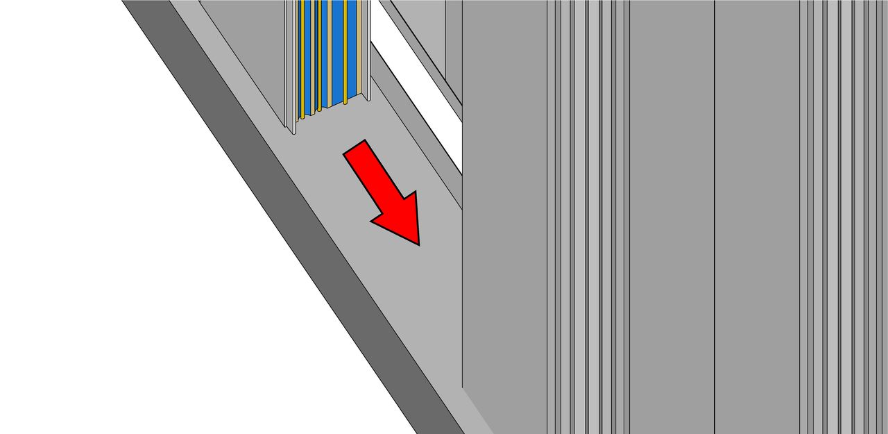
Place the panel onto the structure, press down and screw with fasteners. Repeat steps 1-5.

Downloadable pdf file with instructions here.

Possible inquiries / consultations at +48608 064 085 or e-mail: kk@europanels.pl
Poltherma DS – 1 – Preparation for installation of the panels

1.1. Preparation of assembly elements

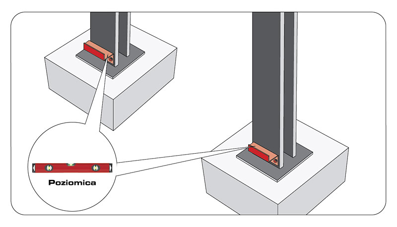
In some cases, it is possible to have a horizontal, single-span layout of PolTherma DS sandwich panels, fixed only to supporting columns. This allows the use of a lightweight support structure – the columns are set on the footings, and the panels are fixed to the columns, without supports (transoms). For buildings that do not require footings, this solution is advantageous due to the reduction of material and labor costs already at the construction and execution stage.

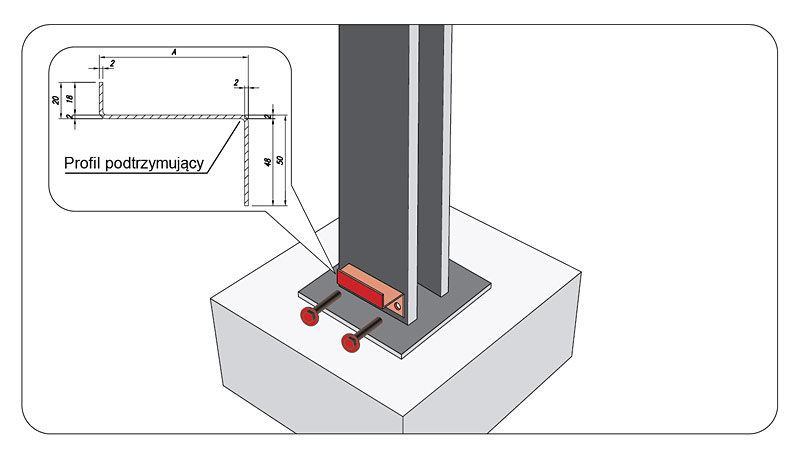
The installation of the panels is preceded by the preparation and installation of support zet profiles to the beams. Supporting zetches should have a length equal to the width of the column. The shape and dimension of the zetizer is shown in Figure 1.1. Since the supporting Z profile is a structural element, its use should be provided for in the design of the structure. The Z profile is made on the construction site or in the preparation workshop.

1.2. Installation of the Z profile to the beams

Starting profile for DS panels

Panel thickness D [mm]. A [mm]. Sheet thickness [mm] Expansion [mm]. Lengths [mm]. Element weight [kg].
50 32 2,0 102 300 0,48
60 42 2,0 112 300 0,53
80 62 2,0 132 300 0,62
100 82 2,0 152 300 0,72
120 102 2,0 172 300 0,81
160 142 2,0 212 300 1,00

Supporting risers are always made of 2 mm thick flat bar. Z profiles are installed in the axis of the columns in such a way that the panels resting on them forms an even starting line for the installation of the other sandwich panels. Therefore, the most important thing is to level the Z profiles on the entire support structure.

Z profiles are attached with screws to the beams or by welding.

1.3. Wall panels securing

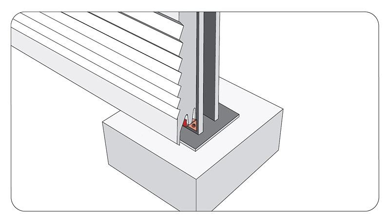
After mounting the leveled support Z profiles to the columns, you can proceed to install the panels. The outer spline of the zet should enter the outer groove (covered by the nose) of the panel. When the panel rests with all its weight on the Z profiles, it is fastened from above to the column using a set of load distributor and 2 fasteners per fastening point (see description on the next page).

Poltherma DS – 2 – Installation of wall plates to steel contruction

2.1. Removal of protective film

It is imperative that the protective film be removed from the surface of the panel no later than one month from the date of manufacture, but in times of high temperatures immediately after delivery. The film only performs the function of protecting the cladding from scratches in transport and installation. To prevent the effects of high temperatures, packages should be covered with a white tarp.

Due to sunlight, leaving the film can result in its vulcanization, which is difficult to remove, unsightly and it is not covered by the warranty. The manufacturer is not responsible for the removal of the film.

TIP: The protective film is applied to the entire surface of the panel.
Remember that the filming can be double-sided!

2.2. Method of fixing- load distributor

For the installation of all PolTherma DS series sandwich panels, regardless of their thickness and profiling, it is necessary to use a special load-distributing washer, the so-called “load distributor”. The distributor is in the form of an angle bracket with holes that allow you to adjust the spacing of the screws for different support profiles. There are two mounting screws for each one load distributor.

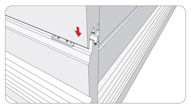
A set of distributor plus mounting screws is placed in the specially shaped part of the panel lock. This makes the screw heads invisible from the outside.

Before you attach the board to the structure, make sure that you have previously applied the acoustic tape from the EuroPanels range.

2.3. Installation of following panel

The installation of the first panel is very important, as it sets the level for the subsequent panel, which rest horizontally one on top of the previous one.

With the first panel leveled and screwed in place, the next sandwich panel overlaps it on a tongue-and-groove basis, covering up the so-called “tongue and groove” nose lock with fasteners.

Make sure that the panel rests with all its weight on the previous one and fix it by repeating the action from the previous step.

Poltherma DS – 3 – New generation 046 corner flashing installation

The new generation of Europanels corner flashings with concealed fastening has been developed primarily for the aesthetic finishing of the corners of buildings made of sandwich panels, installed horizontally.

3.1. Auxiliary handles (base) 047

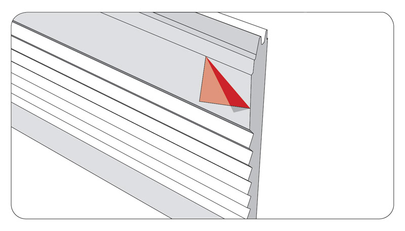
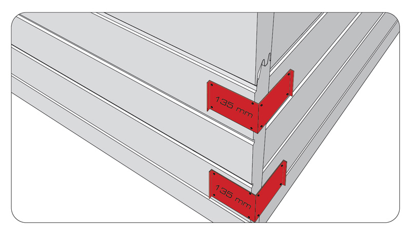
After the sandwich panels are attached to the structure, the installation of the corner flashings begins with the arrangement, leveling and screwing of auxiliary brackets 047 to the panel facings.
They have one fixed dimension (135mm) and another variable dimension, depending on the thickness of the wall panels used on the site. If the plates come together at the corner to the face (not sheared at an angle of 450), the side of the angle bracket of fixed dimension should fall on the panel without joining, and the other (variable) should overlap beyond the joint of the panels.
For 1 piece of external flashing 046 with a length of 2.5m, there are 4 pieces of brackets 047. Handle spacing: one at each end of the flashing, and the other 2 at a distance of approx. 1m apart. The end brackets should remain visible after installation. Only the first flashing section should align flush with the bottom bracket edge, and the last section with the top edge.
Support brackets are mounted to the surface with sheet metal screws or farmers. There are four fasteners per bracket piece, located at the corners, at a distance of approx. 25 mm from the edge of the handle.

3.2. Corner bracket installation 046

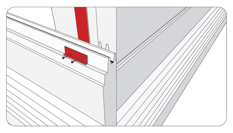
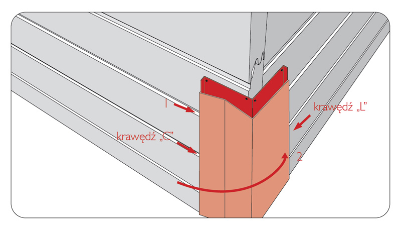
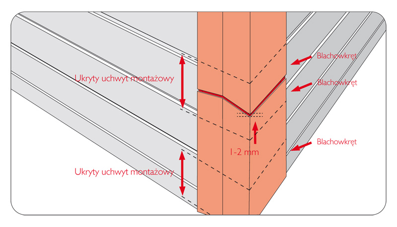
After such preparation of the mounting brackets, you can proceed with the installation of the external angle 046. One edge of the flashing (with profiling) is bent into a “C” shape, the other (variable, unprofiled) into an “L” shape. First, insert the “C” edge into the gap between the surface of the sandwich panel and the auxiliary bracket (step 1), and then position the flashing so that the other side remains ok. 1mm of space between the edge of the flashing and the panel facing (step 2).

When installing the flashing, pay attention to the sharp “L” edge. Taking precautions will avoid possible injury to the body and scratching the cladding of the sandwich panel.

3.3. Final assembly

This type of flashing is not designed to be joined along its length with an overlap (i.e., it does not overlap). For this reason, they are symmetrical, and at the point where they are joined along their length there should be a gap of approx. 2mm.

The 046 flashing is fastened on the “L” side with mini-sheet metal screws or steel tight rivets to the profiled element of the 047 brackets in four places, i.e. one sheet metal screw on each auxiliary bracket per flashing. When installing, make sure not to scratch the cladding of the sandwich panel when drilling / screwing.